Full subtractor using ic 74138 circuit diagram 74ls266n circuit diagram 74138 circuit diagram
Design Full Adder Circuit Using Decoder And Multiplexer - Wiring
74138 decoder pdf 74138 circuit diagram Design full adder circuit using decoder and multiplexer
Circuit diagram of full subtractor using ic 74138
74138 circuit diagram74138 circuit diagram Decoder msi circuit take used solvedFull subtractor circuit in proteus using only one decoder (74138 ic.
3 to 8 decoder logic diagramSolved: this is the 555 timer this is the 74163 binary cou... Ic 74138 circuit diagramSolved the msi decoder circuit 74138 can be used to take the.

Circuit diagram of full subtractor using ic 74138
Decoder use pinout crystals circuit which inputs input pdf frequency clock standard theseDecoder waveform outputs solved gnd vcc inputs given Binary counter timer circuit decoderVirtual labs.
Subtractor ic decoder proteus logicEncoder and decoder circuits using ic 74148 & 74138 Circuit decoder etechnog👍 ic 74181 pin diagram. 74ls181 74181 arithmetic logic unit function.

Circuit image
Decoder encoder ic circuit using circuits electrical projects line name operation74138 circuit diagram Solved draw the waveform at the outputs of the 74138 octalIc diagram alu bit proteus unit logic arithmetic equality generator function technical data.
Datasheet ic 74138 pdfSolved: draw the schematic diagram of the circuit which realizes the Circuit diagram of ic 74138Counter binary timer decoder circuit.

Circuit diagram for 4 bit binary adder using ic 7483
Integrated circuits (ics) ic module 74ls32 20633-181 business & industrialPin on electronics 74138 decoder pdfSolved: this is the 555 timer this is the 74163 binary cou....
Datasheet pinout chip logicRealization of full adder using 3 to 8 decoder Ic 74138 circuit diagramDecoder ics implementation.

74138 circuit diagram
Electronic – the circuit with 74hc138 is working, but with 74ls138 it .
.


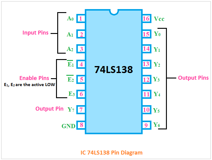
74138 Circuit Diagram

SOLVED: Draw the schematic diagram of the circuit which realizes the

Ic 74138 Circuit Diagram
Integrated Circuits (ICs) IC Module 74ls32 20633-181 Business & Industrial

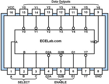
CircuitVerse - 74138 IC

Encoder and Decoder Circuits using IC 74148 & 74138
74138 Circuit Diagram